|
Product Details
Home>
Product Details
|

- 商品详情
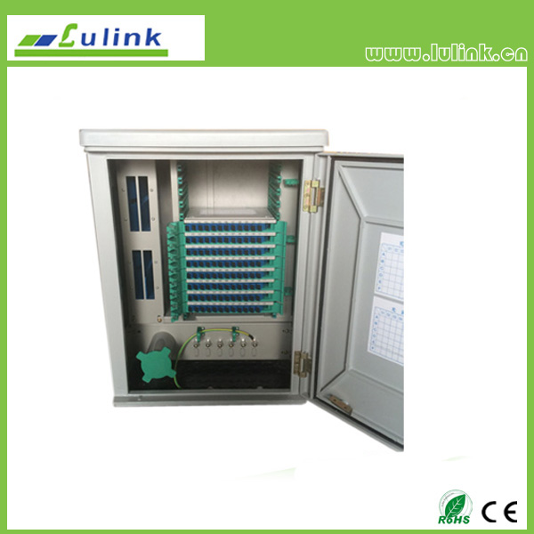
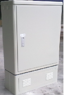
The new 144-core optical cable transfer box Instructions
Overview
1. This product is used in optical fiber access network trunk cable and wiring cable connected device nodes can achieve optical fiber splice storage and scheduling functions. Technical standards with YD / T988-2007.

2. Features
1) Box of high-strength corrosion resistant unsaturated polyester SMC special synthetic material with high heat resistance, can withstand drastic changes in climate and poor working conditions.
2) Lock box with positioning, born long brand lock, safe and reliable.
3) Can interconnect cable, cross-connect and optical disk storage.
4) Reliable cable fixing and grounding protection devices.
5) Use welding wire integrated module for FC, SC fiber optic adapter card installed; and into the light distribution splitter.
6) Fiber distribution and scheduling are all front operation.
3. Technical specifications
1) Conditions
Ambient temperature: -20 ℃ ~ + 60 ℃
Storage temperature: -25 ℃ ~ + 55 ℃
Relative humidity: ≤95% (+ 40 ℃ when)
Atmospheric pressure: 70Kpa ~ 106Kpa
2) Optical Properties
Connector insertion loss (including insert, swap, repeat) ≤0.2dB
Return loss: FC / PC≥45dB FC / UPC≥50 dB FC / APC≥60 dB
Plug durability life of more than 1000 times.
4. Box features
1) Chassis enclosure protection: GB4208 / IP65
2) Static load capacity: ≥980N side surface of the enclosure door hinge ≥200N ≥500N
3) Insulation resistance: high-voltage protection with rack insulation resistance greater than 1000MΩ (500V / DC)
4) Withstand voltage strength: high-voltage protection with the chassis through the DC 3000V for 1 minute without breakdown and flashover occurred.
Specification
1. Product Dimensions: 1035mm * 525mm * 310mm (H * W * D)
2. Maximum Capacity: 168 cores (typically 144 cores)
Installation
1) prefabricated cement base, pictures as follows

Cement base dimensions (length x width x height) of 590mm * 420mm * 300mm, ground center left into the hole line of 405mm * 170mm * 300mm.
2) Embedded foot screws ensure foot from the center of the screw is 438mm * 180mm, screw up the horizontal 50mm (or expansion bolt).
3) The cabinet on the cement base, and its fixing holes with embedded ground screw properly aligned, then the ground screw locked box should be installed so that the cement base and maintain the vertical level. In the case of existing cement base, with four M10 x 60 expansion screw can be fixed.
Usage and Operation
1) Box open
Through a special key to open and close the door.
2) Fiber optic wiring principle
Using fiber optic cable and fiber optic cross-connect mode. Namely cable and wiring pigtail into the office, out of the cable and other wiring pigtail were fused and into the side. Between cross-connect jumper pigtail.
3) Cable access and fixed
Cable into the box from the bottom of the box. After the cable into the box with a cable stripping knife to the protective layer, stripping length decision based on the actual situation, the cable in place with a hose clamp stripping cable fixing plate fixed in the box; and the fiber optic cable to strengthen the core fixed to the mounting plate The cable core fixed shaft.
4) Fiber optic splicing
Remove the fuse with the module cover, front fiber optic splice protection sleeves penetrate the core, and then ends with the pigtail cable core core cable splicing process ends by welding, and then the disc into the melt with one module of splice trays . Welding good pigtails, introduced into the melt with one module distribution panel, and inserted into the appropriate adapter.
5) Double pigtail (jumper) connections
The weld fused with the module into the box good, the double pigtail (jumper) ends respectively inserted into the appropriate adapter, the remainder fiber plate line ring, complete a fiber optic link.
6) Disc fiber and connector PLC splitter
The Micro PLC splitter 495 Used melt glue with integrated fixed internal tray, and then branch to introduce fiber winding disk tray. Then the input and output terminals PLC splitter screw on the corresponding model of the adapter card connected to the Fused with integration tray slot can be.
